
Frequently Asked Questions
Material flow problems happen when bulk materials stop moving smoothly through bins, hoppers, silos, chutes, or other handling equipment. Common symptoms include bridging, ratholing, buildup, clogging, slow discharge, and inconsistent feeding. The following picture shows images of common flow issues.
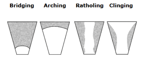
Flow issues can be caused by moisture, compaction, particle size, material stickiness, equipment geometry, vibration frequency, discharge opening size, or the way material settles in the container.
No. Global Manufacturing notes that many flow problems causing major aggravation can be solved with economical, straightforward flow-aid solutions rather than complicated system changes.
Helpful details include the type of material, material density and characteristics, bin or hopper dimensions, wall thickness, discharge opening size, current flow issue, operating environment, and any existing vibrator or air cannon equipment. Pictures or 3D models help immensely in our understanding of your processes so we can help you find the root of your problem.
Customers can call Global Manufacturing during business hours for free application help, use the website’s how-to guides and calculators, or contact the company by email after hours.
Global Manufacturing is located at 1801 East 22nd Street in Little Rock, Arkansas, and provides support for customers in the U.S., Canada, and international markets.
Industrial vibrators apply controlled vibration to pass through a bin, hopper, chute, or similar vessel to the material so it can break loose, reduce buildup, and move more consistently toward the discharge point.
The right solution depends on the material, container size, wall thickness, hopper shape, flow problem, and operating conditions. Global Manufacturing provides how-to guides, selection guides, online calculators, and application assistance to help narrow the choice.
Yes. Global Manufacturing offers plenty of online support through our online calculator for rotary vibrators, how-to guides, and selection guides for rotary and piston vibrators so customers can match equipment to their application. We are also available for complimentary application assistance to help solve your material flow issues.
The first step is to determine the maximum weight of the bulk material that needs to be vibrated. We recommend calculating this from the volume of the sloped portion of your hopper in the sloped portion of the hopper and density of the material.
Typical sizing inputs include the hopper style/design, the dimensions of the sloped portion or problem section, and the density of the stored bulk solid.
The sloped portion is important because that is where material will start to build up due to surface friction between the bin wall and material. Vertical walls tend to flow regularly in most applications. You don’t want to size a vibrator for the total hopper volume when only one section is the issue; this will result in a vibrator too large for the application.
The calculators help users select the hopper style, enter the hopper dimensions, add material density, and estimate the amount of force needed for the application. This is the recommended force to move material in the section in question if FULL. If the amount of material is less than full when issues arise, lower force may be required.
For materials with density less than 90 lb/ft³ or flows freely under normal conditions, the guide recommends using approximately 1 lb of force for every 10 lb of material.
For materials with density greater than 90 lb/ft³, sticky, high in moisture, or prone to bridging, the guide recommends approximately 1 lb of force for every 5 lb of material.
If the material has mixed characteristics, such as being heavy but free-flowing or lighter but prone to cling or bridge, the guide suggests using approximately 1 lb of force for every 8 lb of material.
No. The ratios are approximations based on field experience. They are useful guidelines, but the best selection should still consider the specific material, equipment, and operating conditions. Many of our vibrators have adjustable weights which allows you to turn the force up or down.
Frequency describes how rapidly vibration energy cycles, while amplitude describes the height of the vibration movement. Together, they determine the force produced by the vibrator. Frequency can be easily reference by the RPMs produced by the vibrator and the Amplitude can be referenced by the actual force output measured.
Yes. In general, finer materials respond better to higher-frequency vibration (higher RPMs), while coarser materials often need higher force (higher pounds-force) to move effectively.
Examples of fine materials include cement, flour, sand, and powders.
Examples of coarse materials include aggregates like rock, gravel, coal, and ores.
Customers should gather the material and hopper information, use Global Manufacturing’s calculators and selection guides, and contact Global Manufacturing for application assistance before making a final selection. We are happy to help!
Even the right vibrator may not perform well if it is not mounted correctly. Proper mounting helps transfer vibrational energy through the hopper, bin, chute, or other equipment to the material. This allows the material to move without damaging the structure or vibrator.
Proper mounting is the key to successful vibration because it helps transfer vibration energy through the structure and into the material where it is needed. Poor mounting can reduce performance, increase noise, and damage the vibrator or structure.
No. Global Manufacturing’s mounting guidance warns against mounting the vibrator directly to the structure wall because it can damage the bin or hopper and may not transfer energy correctly.
A channel iron should be used as a stiffener and as the transducer that transfers vibration energy into the structure while helping prevent the wall from flexing excessively.
For starters, the channel iron should be wide enough to mount the vibrator to it. For many hopper applications, the channel iron should be at least two-thirds the height of the sloped portion of the hopper, but generally no longer than 10 feet. Our Guide, How to Mount Industrial Vibrators, has a list of recommended channel irons for each vibrator with minimum lengths.
The channel iron should be stitch welded vertically to the sloped portion of the hopper wall. A common pattern is to weld 3 inches, skip 1 inch, and continue that pattern along the channel. Do not end the ends of the channel iron.
Leaving the ends and corners unwelded allows vibration energy to dissipate from the ends of the channel and helps reduce the risk of stress cracks in the hopper or bin.
A rotary vibrator is typically mounted at the center of a vertically oriented channel iron on the sloped portion of the hopper so vibration can reach along that whole bin wall. The rotation needs to be in the direction of desired material flow. When multiple vibrators are used on a hopper, location of each vibrator can be offset from center to help the vibration from each vibrator reaches more areas of the bin or hopper.
When a rotary vibrator is mounted correctly, the vibrator should appear nearly motionless. Excessive visible movement or noise may indicate a mounting problem.
A piston vibrator produces linear shock waves that rapidly and repeatedly deflect the hopper wall. This action is sometimes described as oil canning and can help restore material flow. The shock wave also has the ability to move the material off the bin wall.
The channel iron helps distribute the linear vibration energy and supports the hopper wall, so the vibration works on the material without overstressing the structure.
The channel iron for a piston vibrator can be shorter than a channel iron for a rotary vibrator as the impact force is more focused. A channel iron that is too long will reduce the impact force imparted on the material and reduce possible oil-canning.
No. Vibrators should not be operated when the structure is empty because doing so can cause structural damage to the structure, vibrator, or both.
No. Operating a vibrator while the gate is closed can compact the material instead of helping it flow. This will make the material even harder to move when needed.
A safety cable or chain should be attached from the vibrator to an independent stronghold to help support the unit if mounting hardware fails.
Mounting techniques can vary by vibrator model and application. The product operations manual provides model-specific details such as bolt size, torque, orientation, electrical or air requirements, and safety instructions.
Customers should review the mounting guide, check the product operations manual, and contact Global Manufacturing’s customer service team for application-specific mounting support.
An air cannon may be useful when a sudden, powerful blast of air is needed to break up stubborn blockages or restore flow in applications where vibration alone may not be the best solution. Applications involving particles that can make a cohesive bond, like wood chips and biomass, are great applications for air cannons. They are also great in “cleaning” bin walls, like the vertical walls in a silo.
An air cannon, also known as an air blaster, is a blast aerator that stores compressed air in a pressure vessel and releases it through a quick-opening valve in a sudden, high-energy burst to help restore material flow or clean material clinging to silo walls.
An air cannon may be the better choice when material is too cohesive, too difficult to dislodge with vibration, too moist, or when equipment conditions make effective vibrator placement impractical. They are also more suitable for material clinging to vertical walls.
Materials such as wood chips, pulp, high-moisture materials, sticky bulk solids, material with pasty or greasy consistency, or light and airy materials may require air cannon assistance.
Yes. Concrete silos generally cannot be effectively vibrated, so air cannons can be a practical flow-aid option for these structures.
Air cannons are selected and placed by their area of influence. This area can be affected by many factors but the main ones are: internal tank pressure, tank volume, discharge size, and speed of valve movement.
Global’s air cannon models are based on temperatures it can withstand. Our standard-duty air cannons are our GW and GWE Series. They are intended for applications where ambient temperatures remain between 0°F (-18°C) - 130°F(54°C). G400 Series high-temperature air cannons are designed for extreme-temperature environments where the temperature seen at the valve is 0° (-18°C) - 400°F (200°C). Our subzero air cannons were designed for colder climates and can withstand ambient temperatures of -40°F (-40°C) - 400°F (200°C). These can reach lower temps if you special order a stainless steel tank.
High-temperature air cannons are often used in demanding environments such as cement kilns, steel mills, and other high-heat or corrosive environments.
The primary information to drive using an air blaster is the type and makeup of the material, the bin design, and what success means. Useful material information includes material density, whether the material is dry or sticky, whether it compacts or clings, particle size, moisture level, and whether it flows easily under normal conditions. Bin design can create challenges for vibrators that air cannons can beat. And lastly, if success is cleaning out all the material, air cannons are key to accomplishing that.
The selection guidance separates materials into 2 types: Type I and II. These are based on factors such as weight, particle size, clinging behavior, dryness, and how easily the material flows during storage.
Type I materials generally include heavier solids, materials with mixed sizes or large chunks, materials that cling regardless of weight, and materials with pasty or greasy consistency.
Type II materials generally include lighter, dry, powdery solids that do not compact or cling during storage and usually flow easily under most conditions.
Helpful details include the diameter or width of the structure, the location of the blockage, the discharge opening, available mounting space, operating temperature, and material makeup of the bin walls.
The number depends on the material type, structure size, factory air available, area of influence, severity of the flow problem, and what success looks like. Global Manufacturing provides a selection chart to help estimate the recommended quantity per bin or hopper in a simple application. Hopper designs are getting more complicated and there is not an easy metric. Please call us for assistance.
Customers should review the flow problem, identify the material type and storage geometry, check temperature and space limitations, consult the selection chart, and contact Global Manufacturing for application support when needed.