
CONSOLIDATING CONCRETE - Basic Concepts and Techniques
“Concrete kän-krēt n. - a hard strong building material made by mixing a cementing material (commonly Portland cement) and a mineral aggregate (such as washed sand and gravel or broken rock) with sufficient water to cause the cement to set and bind used in the constructing of bridges, buildings, dams, pavements, tunnels and smaller projects." (Webster's Third New International Dictionary)
Concrete has been used as a building material since Roman times. It is extremely versatile and durable, as the many ancient concrete structures that remain intact thousands of years after erection will attest. Today, concrete is considered the most widely-used building material in the world.
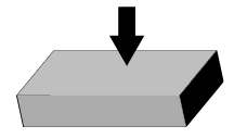
By definition, concrete consists of three major elements - cement, aggregate and water - however, when freshly-poured concrete is placed into a form a fourth element is introduced - air. This entrapped air can comprise as much as 30% of the volume of freshly-poured concrete. The purpose of consolidation is to remove as much of this entrapped air as possible.
Why consolidate concrete? Why remove the air?
If the entrapped air is allowed to remain in the concrete during the curing process, and the concrete is not completely consolidated, the finished volume of the concrete may be as much as 30% greater than intended. The entrapped air, present as honeycombed pockets as well as smaller voids, creates weak points that will significantly lower the working strength of the cured concrete.
Once properly consolidated, the resulting concrete will be more homogenous, have fewer cracks and voids, be significantly stronger and more durable, less permeable and will have an improved finish with fewer visible flaws. In short, it will have become concrete.
What is Slump?
Among other differences, concrete can be made with varying percentages of water and many different sized aggregates. The Slump Test (ASTM C 143) is a standardized method of classifying the “workability” or “flowability” of wet concrete. The test measures the amount of “slump” or the effect of gravity on a concrete sample. The lower the number (the less slump) the drier the mixture is. Higher slump test values indicate more plastic or flowable concrete mixtures.
How is concrete used?
Concrete is widely used as a building material because of its high compressive strength. However, unless reinforcing elements (such as steel reinforcement or rebar) are incorporated, concrete has very low tensile strength.
Compressive Strength - the ability of a material to resist applied pressure without cracking or becoming permanently deformed.
Tensile Strength - the ability of a material to resist being stretched or pulled without cracking or becoming permanently deformed.
A concrete structure can bear a tremendous weight, so long as the load is applied in compression. Since the presence of entrapped air in freshly- poured concrete is known to lower the compressive strength of the cured concrete, any concrete that is intended as a structural or load-bearing component must be properly consolidated.
Methods of Consolidation
There are two basic methods used to consolidate concrete:
- Manual or mechanical tamping
- Vibration
Which method is used is largely dependent on the desired results. Low-compression or non- structural components (sidewalks, small pads, etc.) are occasionally manually consolidated. However, this method does not produce a finished product that is capable of withstanding any significant compression or tensile stress. To achieve a finished concrete product that meets these requirements, consolidation by vibration is strongly recommended.
Vibrating Concrete
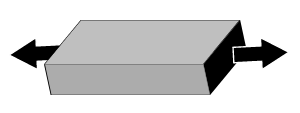
Consolidation by Vibration is achieved by adding a mechanically-induced combination of force and frequency to gravity and allowing those forces to act on the freshly-poured concrete. The proper combination of force and frequency will result in fluidization of the concrete ensuring that the concrete will retain its homogeneity while seeking its lowest level and allowing the entrapped air to escape through the surface.
Initially, the force component of the vibration causes rapid disorganized movement of mixture particles within the vibrator's area of influence. The mortar is temporarily liquefied. Internal friction, which enabled the concrete to support itself, is reduced by up to 95%. The mixture becomes unstable and gravity causes the concrete to seek a lower level and denser condition. A frequency of 9,000 - 12,000 vibrations per minute initiates resonance in (or “excites”) the cement, causing the ultra-fine cement particles to release the extremely small air pockets that have adhered to the cement, so that the mortar fills in all of the spaces around the aggregate. The concrete will flow laterally as restricted by the formwork and around the reinforcing steel embedments. This movement causes both large and small pockets of entrapped air to rise to the surface.
Once enough of the entrapped air has risen to the surface to achieve concrete consistent with the intended strength of the mixture, the vibration is complete. In practical terms, it is neither possible nor necessary to remove all of the entrapped air in the consolidation process.
Types of Vibrating Equipment
Concrete Vibrating systems can be categorized as:
External VibratorsThe vibrator is affixed to the formwork or a platform.
The vibrating mechanism is inserted into the freshly poured concrete.
Contractors select either or both equipment styles based on the finished product requirements, jobsite conditions or other factors.
Internal Vibrators
All internal vibrators achieve consolidation by means of a vibrating head that is inserted directly into the concrete. An eccentric (unbalanced) weight spins at a high rate to produce the vibrations in much the same way as an out-of-balance tire will cause an automobile to vibrate. These vibrations emanate from the vibrating head at right angles to the head. The Radius-of-Action of the vibrating head is determined by the frequency and amplitude of the vibration and is subsequently affected by the consistency of the concrete and the characteristics of the form.
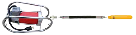
The most common Internal Vibrator style is a Flexible-Shaft Vibrator (sometimes referred to as a spud or poker vibrator). The power is generated by a remote motor that remains with or near the operator. Motors are typically standard 120V or 240V Electric Motors, specialized Pneumatic Motors, or Gasoline Engines. The power is transferred to the Vibrating Head by a two-part flexible drive shaft consisting of an internal rotating core and an exterior protective casing. In this design the power cord (or air supply) remains at or behind the operator, allowing for versatile and easy movement on the jobsite. The use of quick-disconnect couplers and different power sources provides additional flexibility for the operator.
A less-common style of Internal Vibrator is known as a Motor-in-Head Vibrator. In these vibrators, both the electric (or pneumatic) motor and the eccentric weight are located within the vibrating head. In this system, the energy supply needed to power the motor and rotate the eccentric weight must be delivered to the vibrating head by means of a power cord or air hose that is also immersed in the concrete.
The motion of a vibrating head is generally described in terms of Frequency (the number of vibrations per minute) and Amplitude (the deviation of the head from the neutral position as it oscillates). The Centrifugal Force generated is typically expressed in pounds, since acceleration (g-force) is difficult to determine because the amplitude in concrete cannot be easily measured.
Two factors (the speed the eccentric weight turns and the unbalance of the eccentric weight) determine the force that is produced and the subsequent the Radius-of-Action of the vibrating head. This is important because the vibrator head is repeatedly inserted and removed to ensure that the entire structure is properly consolidated. (Insertions are normally made at approximately 1.6 x the Radius of Action to ensure adequate overlapping.) In practical terms, larger diameter vibrators will have larger areas of influence and require fewer insertions. Additionally, lower-slump concrete (because of the lower moisture content) will require greater force levels to initiate the first stage of consolidation - liquefying of the mortar - so larger diameter heads are recommended for low-slump mixtures.
While Internal Vibrators are the simplest and most common method of vibrating concrete, and typically provide uniform compaction, the operator-induced variables (number and proximity of insertions as well as duration of immersion in the concrete of the insertion) may require somewhat more supervision and training in the use of Internal Vibrators to ensure proper consolidation.
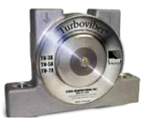
External Vibrators
External Vibrators remain “outside the pour” and deliver the vibration to consolidate concrete through the formwork. External Vibrators are commonly used in production (precast concrete) where there is consistency of concrete mixture, formwork, power source, etc. Once the proper locations, frequencies and durations have been determined, External Vibrators do not rely so much on the skill of the operator as with Internal Vibrators.
External Vibrators are also increasingly used on jobsites where “rebar congestion” is becoming more prevalent. In these cases, it simply becomes impossible to make an adequate number of insertions with an Internal Vibrator.
Because the energy to consolidate the concrete travels from without the form to within, External Vibrators are often used whenever a higher-quality exterior finish is desired. Occasionally, small high- frequency External Vibrators are used to provide an improved surface finish following consolidation.
Because of the frequency requirement for optimum consolidation, the most common External Concrete Vibrators use compressed air (pneumatic) to provide the power to rotate the eccentric weight. Occasionally hydraulic and electric motors are also used, though their lower frequencies will reduce the effectiveness of the vibration. External vibrators may be mounted to the formwork using fixed or removable brackets to facilitate relocation of the vibrators as the wet concrete is placed into the formwork.
As with Internal Vibrators, External Vibrators use a rotating eccentric weight to produce vibrational force. The force emanates from the vibrator in directions both perpendicular to and in plane with the form. A sinusoidal wave of energy is transmitted into the concrete and induces consolidation. The area-of-influence of the external vibrator is determined by the frequency and amplitude of the vibration that is generated, and is also affected by the consistency of the concrete and the characteristics of the form. This area-of-influence takes the shape of a slightly flattened hemisphere, with the greatest penetration into the concrete directly in line with the vibrator.
Lower-slump concrete and heavier formwork requires higher force vibration, while higher frequency vibration is more effective for higher slump concrete and lighter weight forms. External Vibrators may be located on one or both sides of the formwork and occasionally supplemental vibration using Internal Vibrators is required.
Once proper locations and methods of mounting the vibrators and optimum vibration durations are determined, External Vibrators provide a consistent and effective method of compacting the concrete. Due to variables in formwork and concrete consistencies, using External Vibrators may require additional preparation and planning to ensure satisfactory results.
How to Select an Internal Vibrator System
Power Units - The first decision when selecting an Internal Vibrator is to determine which power source will be used. These criteria include:
- What equipment the contractor currently has
- The availability and type of power at the worksite
- Worksite Conditions / Accessibility to the concrete
Head Size / Type - Next, the operator will select the head that is most appropriate for the project. Most projects will use standard Steel Tip heads for effectiveness and longer service life. Rubber-tipped heads may be selected for additional protection for lightweight or aluminum forms. Completely- encased heads (polyurethane or rubber) may be used when epoxy-coated reinforcement is present. Other heads such as low-force or shallow pour heads may be used for special conditions.
For speed and ease of consolidation, the contractor will likely elect the largest diameter head that is feasible for the project. Based on higher amplitude vibration, larger heads will have greater areas of influence; therefore will require fewer insertions at greater interval spacing to achieve proper consolidation. Fewer insertions results in faster working times. Factors that may restrict the use of larger heads include:
- Annular space restrictions (based on reinforcement spacing or “rebar congestion.”) It is important NOT to make unnecessary contact with the reinforcing embedments. The vibration may damage the reinforcement and reduce the structural capacity of the finished concrete.
- Dimensions of the formwork. Operators should avoid allowing the Vibrating Head's area of influence from extending well beyond the perimeter of the formwork as this may place undue stress on the formwork and subsequent failure.
- There is a direct correlation between the slump or workability of the concrete and the head diameter that will be most effective. In general, the lower the slump (the stiffer the concrete mixture) the larger the head used. Higher slump (better flowing) concrete will require smaller head diameters. This is as a result of the additional power that is required in Stage 1 - fluidizing the concrete.
Flex-Drive Length - In general terms, the contractor will prefer to use the shortest flex-drive that will allow complete access to the concrete being consolidated.
Selection Examples
Example A - Contractor ABC has a concrete slab project to be poured several floors above grade. The slab to be poured is fourteen inches thick (1'2” / 0.356 m) and has a significant amount of reinforcements. Average annular openings are four - six inches (4” - 6” / 100 mm - 150 mm). The concrete for the project is plastic with a slump test measurement of seven inches (7” / 175 mm). There is electrical power available, but no readily- available compressed air supply. The contractor is likely to choose between Electric and Gasoline Vibrators. Since the overall area to be consolidated requires numerous insertions, the contractor elects to use electricity as the power source.
- Power Unit VMK-2750 Electric Vibrator
- Head VH24-ST (1-1/2” - 38 mm) Steel Tip Head
- Flex-Drive VDR17-7 (7' / 2.13 m) Flex-Drive
Example B - Contractor XYZ has a tilt wall project to be poured on site. There is electrical power available, as well as several portable air compressors. The contractor may choose Electric, Gasoline or Pneumatic Vibrators. Since there is adequate ventilation, and the area to be consolidated requires numerous insertions, the contractor elects to use gasoline as the power source. The wall section to be poured is twelve inches thick (1' / 395 mm) and has an average amount of reinforcements. Average annular openings are eight - twelve inches (8” - 12” / 200 mm - 300 mm). The concrete for the project is plastic with a slump test measurement of five inches (5” / 127 mm).
- Power Unit VMG-2500BP Backpack Vibrator
- Head VH40-ST (2-1/2” - 63.5 mm) Steel Tip Head
- Flex-Drive VDR17-7D (7' / 2.13 m) Flex-Drive with Quick Disconnect
Example C - Contractor 123 has a structural column project to be poured on site. There is electrical power available, as well as several portable air compressors. The contractor may choose Electric, Gasoline or Pneumatic Vibrators. The contractor elects to use compressed air as the power source. The slab to be poured is forty- two inches square (3'6” / 1.07 m) and thirty feet tall, with a significant amount of reinforcements. Average annular openings are three - four inches (3” - 4” / 75 mm - 100 mm). The concrete for the project is very stiff with a slump test measurement of two inches (2” / 50 mm).
- Power Unit VMP-2000 Pneumatic Vibrator
- Head VH40-ST (2-1/2” - 63.5 mm) Steel Tip Head
- Flex-Drive VDR17-21D (21' / 6.4 m) Flex-Drive with Quick Disconnect
- VDR17-14D (14' / 4.27 m) Flex-Drive with a Viber VCP Coupler
How to Select an External Vibrator System
There is not an exact method or science when using external vibrators for concrete consolidation. Mixes vary, and therefore, consolidation procedures and preferred vibrator styles vary. “Experts” become experts through trial and error. What makes every application different is that the mixes will vary due to the slump, any chemical additives, aggregate sizes/shape, cement content, consistency of the mixture, weather conditions, and even the type of form work used. Following these general rules may be helpful in selecting the number and placement of external vibrators for effective concrete consolidation.
In selecting External Vibrators, the contractor should initially consider the workability of the concrete and the rigidity of the forms. Plastic concrete (slump > 3.0 in.) responds better to high frequency vibration, while stiffer mixtures (slump < 3.0 in.) require higher amplitude vibration to initiate fluidization. While properly-sized external vibrators can be successfully used on virtually any concrete formwork, using a too-powerful vibrator on lightweight forms can cause damage to the formwork. This has caused some contractors to mistakenly believe that external vibrators cannot be used on lightweight concrete formwork.
Vibrator Selection: Depending on specific conditions, external vibrators with speeds between 3,000 and 12,000 rpm may be suitable for form vibration. However, because the natural resonant frequency of Portland Cement is in the 9,000 - 12,000 rpm range, Pneumatic powered vibrators are often the only equipment capable of delivering this necessary frequency.
After determining the approximate combined weight of the formwork and concrete to be vibrated, the contractor should select a vibrator producing the amount of force specified by the table below. It will often be necessary to use more than one vibrator to produce the total amount of force required.
Note - If specific density of the concrete is unavailable, use a standardized weight of 150 pounds per cubic foot (2,400 kg / m 3 ) for approximation.
| Vibrator Selection for Concrete Consolidation | ||
|---|---|---|
| CONSISTENCY | SLUMP | VIBRATOR SELECTION |
| Very stiff concrete | <0.5" | Vibrator force output should be equal to 200-300% of the total weight of the concrete and form. |
| Stiff or stiff plastic conrete | 0.5" - 2.0" | Vibrator force output should be equal to 130-150% of the total weight of the concrete and form. |
| Plastic or flowing conrete | >2.0" | Vibrator force output should be equal to the total weight of the concrete and form. |
Forms should be well made to withstand the strains of vibration.
- If using wooden forms, use screws instead of nails (which may back out with vibration).
- Forms need to be well braced to prevent bulging.
- Joints need to be closely fit to prevent leaking.
- Monitor forms during placement of concrete. Tighten as needed.
Operation
Follow these guidelines when using your Viber® Internal Concrete Vibrator for consolidating concrete:
- Never leave the vibrator running in air. Totally submerse the vibrator head in the concrete. This cools the bearings. Running the vibrator in air without regularly submersing it in the concrete will overheat the bearings and damage the vibrating head.
- Avoid making sharp bends in the flexible shaft.
- Make sure you can see the concrete surface. Use lighting if necessary.
- If possible, place the concrete in evenly dispersed layers no deeper than the length of the vibrator head plus 4-6”. Layers should not exceed 18-20”, otherwise the weight of the concrete can prevent the entrapped air from escaping.
- Keep the vibrator head at least 3-4” from the edge to avoid damage to the forms and possible visual surface defects in the finished concrete.
- Do not allow the vibrator head to touch reinforcements, such as rebar. Vibration can break the bond between the reinforcement and preceding layers of stiffened concrete.
- Let the vibrator head penetrate to the bottom of the layer as quickly as possible under its own weight.
- Keep the vibrator head vertical to minimize voids and enhance the release of entrapped air. For shallow flat slabs, lay the vibrator head horizontally and drag it through the concrete or use our Shallow Pour Head - VH34-SP.
- Withdraw the vibrator head slowly. Be sure concrete fills in behind leaving no hole. Do not attempt to “stir” the concrete.
- Use repeated placements of the vibrator in a
systematic pattern to be sure the entire surface has
been vibrated. The area of action can be observed
by noting how far from the vibrator head bubbles
appear on the surface. Placements of the head
should insure overlapping of the areas of action.
- Note - An approximate radius-of-action (based on average slump concrete and typical conditions) is provided for each Viber Vibrating Head. For approximate insertion spacing, multiply the standard radius-of-action by 1.6.
- E.g., VH20 1½”diameter head (radius-of- action-9½”) x 1.6 = 15¼” insertion spacing.
- When compacting concrete placed on a previously compacted layer, push the vibrator 4-6” into the lower layer. Move the vibrator up & down for 5-15 seconds to “knit” the two layers together.
- Avoid placing the concrete in “heaps”. If it is necessary to flatten a heap, insert the vibrator head around the perimeter of the heap using as many placements as necessary.
- Consolidation is complete when no new bubbles come to the top, a glistening layer of mortar covers the concrete surface, and the “whine” of the motor indicates that the vibrator speed has leveled off.
- Clean all vibrator parts immediately following each use.
Tips and Hints for Using External Vibrators
Proper placement of the external vibrators is critical to ensure that the vibration is distributed over the desired area of the concrete. Depending on the concrete consistency, density of embedments and the quality of the mounting, External Vibrators produce an Area of Influence determined by the force of the vibrator and the duration of the vibrating time.
The following guidelines for spacing External Vibrators have been developed, but contractors should determine specific spacing requirements for each project to ensure complete coverage of vibration and successful consolidation.
| Vibrator Spacing for Concrete Consolidation | ||
|---|---|---|
| CONSISTENCY | SLUMP | DISTANCE BETWEEN VIBRATORS |
| Very stiff or stiff concrete | < 1.0" < 25 mm |
5' Apart 1524 mm |
| Stiff plastic concrete | 1.0 - 2.0" 25 - 50 mm |
6' Apart 1828 mm |
| Plastic concrete | 2.0 - 5.0" 50 - 127 mm |
7' Apart 2134 mm |
| Flowing concrete | > 5.0" > 127 mm |
8' Apart 2438 mm |
Moving one's hand over the form (or for greater accuracy, using a vibrating reed tachometer) will help to locate the limits of the areas of influence of the vibrators. Care should be taken to avoid large gaps between areas being vibrated as well as excessive vibration at specific areas.
Vibrating times for External Vibrators may be longer than for immersed Internal Vibrators. Most operators will initially vibrate for approximately two minutes per lift, and increase or decrease vibrating times as needed. Note that the same criteria should be used to determine when the consolidation is complete (cessation of air bubbles at the top surface, a thin film of mortar on the top surface and a stabilization of the speed of the vibrator).
Concrete should be placed in the forms in evenly dispersed layers (lifts). Lift height should not exceed 20” otherwise the weight of the concrete can prevent the entrapped air from escaping. Vibrators should be operated in conjunction with each lift until the concrete is fully consolidated. As each subsequent lift is placed, additional vibrators should be located (or moved from the previous level) and operated. Some operators prefer to operate the previous lift's vibrators for a short period of time to promote “knitting” of the two layers together.
If the thickness of the concrete to be consolidated is greater than the area of influence of the vibrator, or if a higher-quality finished surface is required on both sides, the contractor should locate alternate vibrators on opposite form walls. For instance, the first vibrator is placed on the front wall and the next is 5' (1.5 m) away but on the back wall. See illustration below
Alternating the vibrators on a concrete form
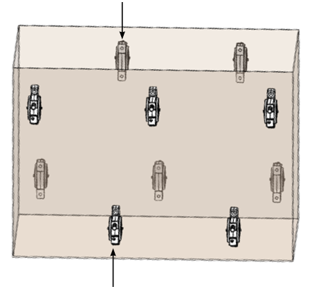 Vibrators on the near side of the form.
In some cases, when the thickness of the concrete to be consolidated is extraordinarily large, contractors may choose to use Internal Vibrators in the center section, with External Vibrators used simultaneously along the outer edges.
Orientation of Vibrator: Whenever possible, the External Vibrator should be mounted with the internal rotating shaft in the horizontal position.
|
|||||||||||||||
|---|---|---|---|---|---|---|---|---|---|---|---|---|---|---|---|
| 1 | 2 | 3 | 4 | 5 | |||||||||||
| Application | Slump | Space Limitations | Head Diameter | Radius of Action | Power Units | Flexible Drive Length (Feet) | |||||||||
| 1 | 3 | 5 | 7 | 10 | 14 | 21 | 28* | 35* | |||||||
| Block Walls & Small Diameter Fills: Plastic and flowing concrete for very thin members & walls & confined places. | >3" | 2.5" x 2.5" | 7/6" VH 14 | 5" | VMK-1500 | x | x | x | x | x | x | x | x | x | |
| VMP TURBO | x | x | x | x | x | x | x | x | x | ||||||
| VMG-1750BP | x | x | x | x | x | x | x | x | x | ||||||
| VMG-2500BP | 7' or longer | x | x | x | x | x | x | ||||||||
| Thinnest Prestressed Sections: Plastic and flowing concrete for very thin members & walls & confined places. | >3" | 3" x 3" | 1" VH 16 | 5" | VMK-1500 | x | x | x | x | x | x | x | x | x | |
| VMP TURBO | x | x | x | x | x | x | x | x | x | ||||||
| VMG-1750BP | x | x | x | x | x | x | x | x | x | ||||||
| VMG-2500BP | 7' or longer | x | x | x | x | x | x | ||||||||
| Thin Prestressed Sections: Plastic concrete in thin walls, columns, beams, precast piles, thin slabs, and along construction joints. | 3 - 5" | 3.25" x 3.25" | 1-1/4" VH 20 | 7" | VMK-1500 | x | x | x | x | x | x | x | x | x | |
| VMP-2500 | x | x | x | x | x | x | x | x | x | ||||||
| VMP-2750 | x | x | x | x | x | x | x | x | x | ||||||
| VMP TURBO | x | x | x | x | x | x | x | x | x | ||||||
| VMG-1750BP | x | x | x | x | x | x | x | x | x | ||||||
| VMG-2500BP | 7' or longer | x | x | x | x | x | x | ||||||||
| Thin Wall Sections and General Use: Plastic concrete in thin walls, columns, beams, precast piles, thin slabs, and along construction joints. | 3 - 5" | 3.25" x 3.25" | 1-1/2" VH 24 | 13" | VMK-1500 | x | x | x | x | x | x | x | x | x | |
| VMP-2500 | x | x | x | x | x | x | x | x | x | ||||||
| VMP-2750 | x | x | x | x | x | x | x | x | x | ||||||
| VMP TURBO | x | x | x | x | x | x | x | x | x | ||||||
| VMG-1750BP | x | x | x | x | x | x | x | x | x | ||||||
| VMG-2500BP | 7' or longer | x | x | x | x | x | x | ||||||||
| General Use: Plastic & stiff plastic concrete in general construction such as walls, columns, beams, pre-stressed piles, and heavy slabs. | 2 - 4" | 3.75" x 3.75" | 1-3/4" VH 28 | 17" | VMP-2500 | x | x | x | x | x | x | x | x | x | |
| VMP-2750 | x | x | x | x | x | x | x | x | x | ||||||
| VMP-3500 | x | x | x | x | x | x | x | x | x | ||||||
| VMP TURBO | x | x | x | x | x | x | x | x | x | ||||||
| VMG-1750BP | x | x | x | x | x | x | x | x | x | ||||||
| VMG-2500BP | 7' or longer | x | x | x | x | x | x | ||||||||
| Stiff Low-Slump Concrete: Stiff plastic concrete in general construction such as walls, columns, beams, prestressed piles, and heavy slabs. | 1 - 3" | 4" x 4" | 2-1/8" VH 34 | 21" | VMP-2750 | x | x | x | x | x | x | x | x | x | |
| VMP-3500 | x | x | x | x | x | x | x | x | x | ||||||
| VMP TURBO | x | x | x | x | x | x | x | x | x | ||||||
| VMG-2500BP | 7' or longer | x | x | x | x | x | x | ||||||||
| Stiffest Low-Slump Concrete: Mass and structural concrete deposited in relatively open forms. | < 2" | 5" x 5" | 2-1/2" VH 40 | 24" | VMP-2750 | x | x | x | x | x | x | x | x | x | |
| VMP-3500 | x | x | x | x | x | x | x | x | x | ||||||
| VMP TURBO | x | x | x | x | x | x | x | x | x | ||||||
| VMG-2500BP | 7' or longer | x | x | x | x | x | x | ||||||||
| Shallow Pours: Plastic & stiff plastic concrete in slabs and other shallow pours less than 12" thick. | 2 - 4" | 4" x 4" | 2-1/8" VH 34-SP | 13" | VMK-1500 | x | x | x | x | x | x | x | x | x | |
| VMP-2500 | x | x | x | x | x | x | x | x | x | ||||||
| VMP TURBO | x | x | x | x | x | x | x | x | x | ||||||
| VMG-1750BP | x | x | x | x | x | x | x | x | x | ||||||
| VMG-2500BP | 7' or longer | x | x | x | x | x | x | ||||||||
| ICF Applications: Plastic and flowing concrete for very thin members & walls & confined places where insulated concrete forms are used. | > 4" | 2.5" x 2.5" | 7/8" VH 14-LF | 4" | VMK-1500 | x | x | x | x | x | x | x | x | x | |
| VMP TURBO | x | x | x | x | x | x | x | x | x | ||||||
| VMG-1750BP | x | x | x | x | x | x | x | x | x | ||||||
| VMG-2500BP | 7' or longer | x | x | x | x | x | x | ||||||||
| 1. Find description in column 1 that matches your application. | |||||||||||||||
| 2. Use column 2 to adjust for any size restrictions due to reinforcements,such as rebar, or other limiting structures. | |||||||||||||||
| 3. Column 3 gives the diameter of the vibrator head needed. | |||||||||||||||
| 4. Select the power unit desired from column 4. VMK units are universal electric motors available in 10 amps (1500), 15 amps (2500 OR 2750), or 20 amps (3500). The VMK-3500 and the models ending with an “L" come with a twist lock plug. The motor with the higher amp rating will consolidate low slump concrete more efficiently. VMP TURBO is a 2hp pneumatic motor. VMG-1750BP is a 1.6 hp backpack mounted gasoline engine (also available as a handheld unit). VMG-2500BP is a 2.5 hp backpack mounted gasoline engine. | |||||||||||||||
| 5. Find the core and casing length desired in section 5. Smart Part Systems with a 7/8" head come with 7/8" diameter flexible drive. All other systems come with a 1-1/16" diameter flexible drive. | |||||||||||||||
| *Note: 28’ and 35’ flex drives require coupling two shorter drives together using a Viber VCP Coupling. | |||||||||||||||
 System Selection Guide